Series: FRC Technical Foundations Unit: 2 — Making It Move Session length: ~3.5 hours (consider splitting: intakes in one session, elevation in another) Prerequisites: Lessons 1–3
A drivetrain moves a known object — itself — from one known place to another. A manipulator has to interact with an object whose position, orientation, and sometimes shape you do not control.
That difference drives everything in this lesson. Your robot will approach a game piece with a few centimetres of positional error and several degrees of angular error, and the mechanism must succeed anyway. A mechanism that requires the game piece to be in exactly the right place is a mechanism that works in the shop and fails on the field.
The solution is not tighter tolerances. It is compliance: designing the mechanism to deform, deflect, or self-align so that a wide range of starting conditions converge to the same end state.
Rule 4.1 — Make the acceptance window as wide as possible, not the positioning as accurate as possible. A funnel that takes a game piece from anywhere in a 300 mm window is worth more than a gripper that needs 5 mm accuracy plus perfect vision.
This is the single best piece of advice in the source curriculum, and it transfers from WRO to FRC without modification: build the game pieces before you design the mechanism.
FIRST publishes drawings and often a field-element bill of materials at kickoff. Make or buy a dozen game pieces in week one. Then prototype against real objects from day one.
Why it matters so much:
Rule 4.2 — Twelve game pieces before any CAD.
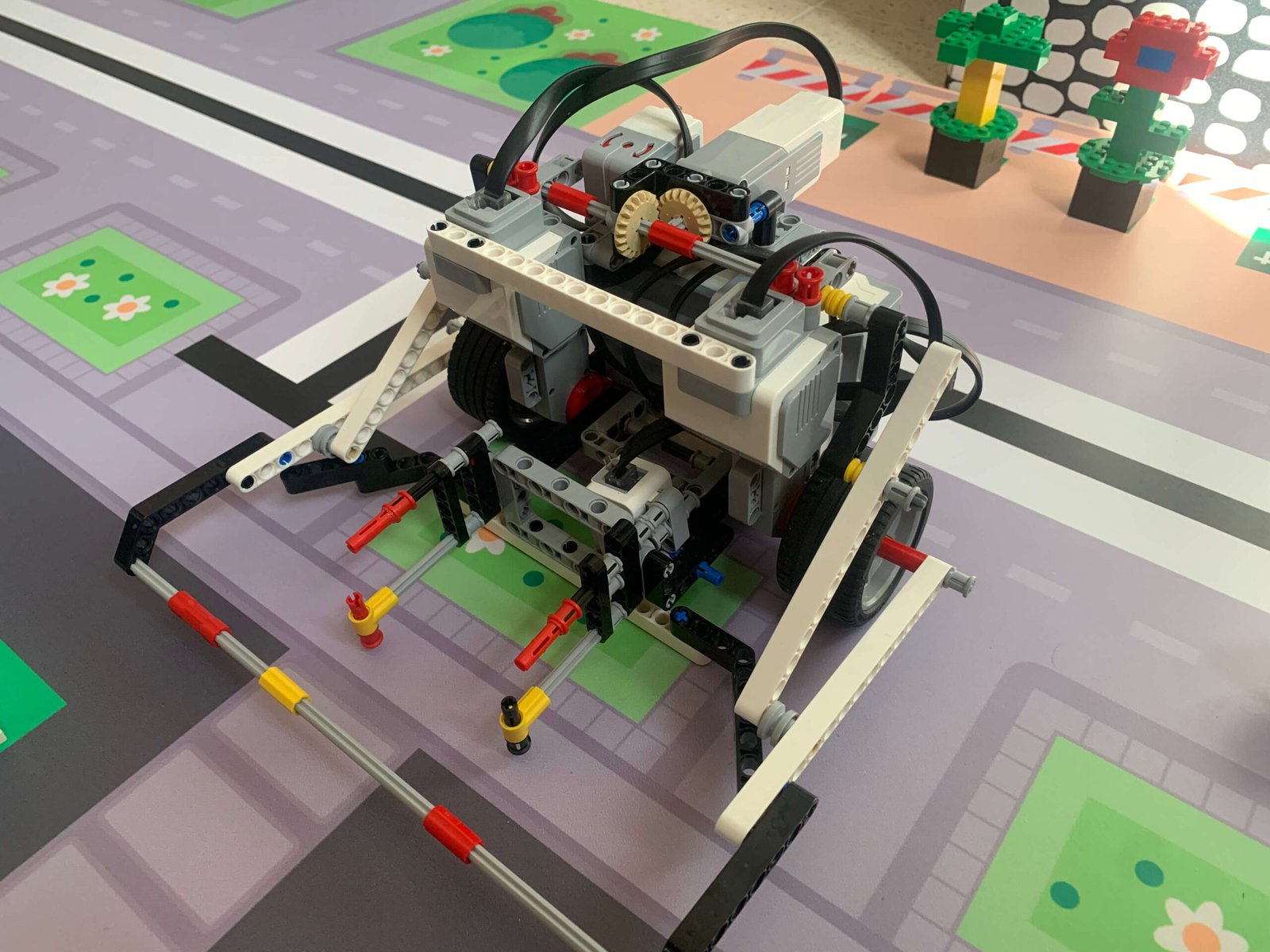
Compliant wheels. Soft polyurethane or rubber wheels that deform against the game piece. They grip over a large contact patch, tolerate misalignment, and forgive being 10 mm too close. The workhorse of modern FRC intakes.
Surgical tubing and flex wheels. Even more compliant, with the deformation designed in. Good where the game piece is fragile or the approach geometry varies a lot.
Funnels and passive guides. Static geometry that mechanically converts a wide entry into a narrow exit. Free — no motors, no code, no failure modes. Every centimetre of funnel you add is a centimetre of driver precision you no longer need.
Over-centre and passive retention. Geometry that holds the game piece once acquired without continuous motor effort. A cradle the piece settles into, a spring-loaded flap it pushes past.
[ANECDOTE SLOT] — A prototype that worked beautifully until it met a real game piece or a real field. Intake stories are usually the best ones; something jamming under a specific approach angle, or a mechanism that only failed when the piece was worn.
Once you have the game piece, you generally need to move it somewhere higher. Three archetypes.
One pivot, one motor, a gearbox. Simple, few parts, robust.
The cost is that the end effector travels on an arc, and the torque required varies as the cosine of the arm angle — maximum when horizontal, near zero when vertical. Your gearing and your control loop both have to cope with a load that changes by a factor of infinity across the range of motion.
The other cost is envelope. An arm sweeps a large area. Check that the swept volume does not intersect your own robot, and remember the extension rules in the game manual.
Two parallel arms connecting the base to the end effector. The end effector stays at a constant orientation throughout the travel — the game piece does not tip as it rises.
This is enormously useful when carrying something that must stay level, and it is why four-bars appear constantly in FRC. The trade-off is more pivots (more bearings, more places to loosen) and a fixed relationship between horizontal and vertical travel that you cannot change after building it.
A virtual four-bar achieves the same effect with a single arm plus a wrist motor geared to counter-rotate. More software, fewer linkages.
Linear travel, usually vertical, on rails or slides.
Cascade elevators use multiple stages that extend together, giving large travel from a compact retracted height, at the cost of rigging complexity — a cascade rig has multiple cable or belt runs that must all be tensioned correctly. Continuous elevators drive all stages from one run, which is simpler but usually means a taller retracted height.
Elevators give you the most vertical travel per unit of retracted height and keep the load directly above the frame, which is good for CG. They also have the most parts to go wrong.
Racking is when the two sides of a linear stage move different amounts, so the carriage skews in its rails and binds. It is the dominant failure mode in FRC elevators.
Causes and cures:
Rule 4.3 — Drive linear stages symmetrically, and spread your bearings. If you find yourself adding motor power to overcome binding, stop. You are hiding a geometry problem, and it will destroy the mechanism.
Every mechanism with a limited range of travel needs both.
A soft limit is in software: the code refuses to command the motor past a position. A hard stop is physical: the mechanism cannot go further even if the code commands it.
You need both because software fails. An encoder cable comes loose, the code thinks it is at zero when it is at full extension, and the motor drives the carriage into the end of the rails at full power. With a hard stop, you bend something and lose five minutes. Without one, you destroy the mechanism.
Rule 4.4 — Hard stops are not optional. Assume the software will be wrong at least once.
Holding a load against gravity costs current continuously, and as we established in Lesson 3, resting a motor at stall is a design error. Counterbalancing removes most of that load.
Never counterbalance to exactly zero net load. Leave enough residual weight that the mechanism falls gently when unpowered, so its safe state is predictable.
Time: 2 × 90 minutes across two sessions. Equipment: Prototyping stock (polycarbonate, wood, kit parts), compliant wheels, motors, a test rig, at least a dozen game pieces, a stopwatch.
Adapted from the source curriculum’s best exercise.
Each group prototypes a different intake concept against real game pieces. Then each group must sell their concept to the room — using data, not claims. A pitch must include:
Groups that pitch without numbers are sent back. The room then scores concepts on a weighted decision matrix agreed before the pitches.
Evidence of learning: A completed decision matrix, one data-backed pitch per group, and a single selected architecture with written justification.
Time: 90 minutes. Equipment: Kit parts sufficient to build two rough elevation concepts, a known payload, measuring equipment.
Build a rough arm and a rough elevator to reach the same target height with the same payload. Compare, with numbers:
Evidence of learning: A five-row comparison table, a recommendation, and a preliminary motor and ratio selection for the chosen concept using ReCalc.
Time: 30 minutes. Equipment: A linear slide or elevator stage.
Deliberately create a racking condition: load one side, loosen one cable run, or apply force off-centre. Observe and record the binding force required to move the stage. Then correct each condition one at a time and measure the improvement.
Evidence of learning: A table of binding force against each induced fault, and a short written diagnosis procedure a pit crew could follow: “elevator is sticky — check these four things in this order.”
Symptom | Likely cause |
|---|---|
Intake works in shop, fails on field | Tested against one pristine game piece; window too narrow |
Intake jams under specific approach | Geometry has a dead angle; add a guide or reverse-on-current |
Elevator sticky in one part of travel | Rail not parallel — frame flex or mounting error |
Elevator binds under load only | Racking from off-centre drive or unequal rigging |
Arm holds fine, then motor gets hot | Resting at stall; needs brake mode or counterbalance |
Mechanism destroys itself once | Missing hard stop; soft limit was the only protection |
Everything so far needs electricity and something to tell it what to do. Lesson 5 — The Control System End to End covers the roboRIO, power distribution, CAN, and why your robot resets in the middle of a match.