Series: FRC Technical Foundations Unit: 1 — Foundations Session length: ~3 hours Prerequisites: Lesson 1
These get confused constantly, so let us separate them immediately.
Strength is the load at which something breaks. Stiffness is how much it deflects before it gets there. In FRC, you will almost never break a structural member. Aluminium extrusion is enormously stronger than anything the game will do to it. What will happen — constantly — is that your structure deflects, and deflection is what actually ruins robots.
An arm that flexes 8 mm under load places the game piece 8 mm off target. A frame that racks 3 mm under a defensive hit changes your wheel alignment and your robot no longer drives straight. A camera mount that vibrates turns AprilTag pose estimates into noise. None of these parts broke. All of them failed.
Rule 2.1 — Design for stiffness, not strength. If you are checking whether a part will break, you are usually answering the wrong question. Ask how far it will move.
Every force applied to your robot has to end up somewhere. It travels through the structure from where it is applied to where it is reacted — usually the floor, through the wheels. That route is the load path.
Good structures have short, direct, continuous load paths. Bad structures have long ones with weak links, and the weak link is almost always a joint or an unsupported span.
Take a concrete case. An elevator carries a 5 kg game piece at full extension, 1.2 m above the frame. When the robot accelerates, that mass generates a horizontal force at the top of the elevator. That force has to travel: game piece → carriage → elevator rails → elevator base plate → frame rail → wheels → carpet.
Ask at every step: is this connection rigid in the direction the force is pushing? The base plate is usually where teams lose it. Four bolts through a thin plate into the top face of one frame rail gives you a cantilever with a tiny moment arm resisting a huge one. The plate bends, the whole elevator leans, and every position the software thought it knew is now wrong.
The fix is not a thicker plate. It is triangulation back down to the frame — a diagonal brace from partway up the elevator to a different frame rail, converting a bending load into a tension or compression load. Structures are vastly stiffer in tension and compression than in bending.
Rule 2.2 — Convert bending into tension and compression wherever you can. That is the entire reason triangles matter.
A four-bar rectangle made of rigid members with pinned corners is a mechanism: it can change shape into a parallelogram without any member changing length. This is called racking. A triangle cannot do this — you cannot change its shape without changing the length of a side, and changing the length of an aluminium tube requires forces far beyond anything on an FRC field.
This gives you three practical tools, in increasing order of effectiveness:
Gussets. A plate across a corner, bolted to both members. Cheap, easy, effective. Their weakness is that they only stiffen one plane, and they rely entirely on the bolt pattern — a gusset with two bolts per side barely helps; four per side starts to matter.
Diagonal bracing. An actual diagonal member across a rectangular bay. The most weight-efficient stiffness you can buy. Ugly, in the way of things, and worth it.
Box structure. Closing the structure into a three-dimensional box — adding a top plate or a belly pan that ties all four frame rails together. A belly pan is not just somewhere to mount electronics. It is a shear panel, and it is often the stiffest single addition you can make to a drivetrain.
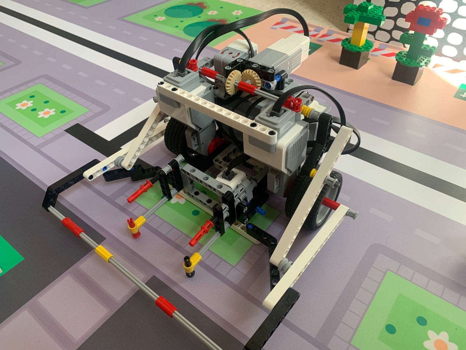
This is a direct scale-up of the WRO principle: avoid long unsupported beams, build closed shapes. At 125 lb and 5 m/s, the principle does not change — only the consequences do.
In LEGO-based robotics the rule is simple: when you connect two parts, use at least two points of contact. A single pin allows rotation, and rotation means your sensor slowly drifts out of position over a dozen runs.
In FRC the same rule holds, but the failure mode is different and worse. A single-bolt joint under vibration does not just rotate — it works loose. Over a six-hour competition day, a single-bolt bracket will back off, and you will not notice until something falls off the robot during elimination matches.
Rule 2.3 — Two fasteners minimum on any structural joint, and spread them apart. Two bolts 6 mm apart resist rotation almost as poorly as one. The resistance to rotation scales with the distance between fasteners, so spread them to the edges of the joint.
Other joint practices worth building as habit:
Rotating assemblies are where rigidity, friction, and alignment all meet, and they deserve the second half of this lesson.
Live vs dead axles. A live axle rotates with the wheel; the shaft is driven, and it is supported by bearings in the frame. A dead axle does not rotate; the wheel spins on bearings around a fixed shaft. Live axles let you drive multiple wheels off one shaft and are standard for tank drivetrains. Dead axles are simpler and stiffer for idler wheels and tensioners. Pick deliberately.
Support on both sides. This is the shaft version of Rule 2.3, and it is the most common mechanical mistake in rookie FRC robots. A shaft supported at one end is a cantilever. Under side load, it deflects, and the gear or sprocket on it goes out of alignment, and the chain skips or the gear mesh binds.
Rule 2.4 — Every rotating shaft gets a bearing on both sides of every load. If a gear sits between two bearings, good. If a gear hangs off the end past the last bearing, you have built a lever whose fulcrum is your bearing, and the bearing will lose.
Bearings vs bushings. Ball bearings are low friction and handle speed. Bushings are cheaper, take more abuse, and tolerate misalignment better. For a drivetrain, use bearings. For a low-speed, high-load pivot that gets hit, a bushing is often the more robust choice.
Retention. A shaft that is not axially constrained will walk. Shaft collars, retaining rings, or a shoulder against a bearing race — pick one, and put it on every shaft. A walking shaft slowly moves a sprocket out of plane until the chain derails.
Alignment is the invisible killer. Two sprockets that are 2 mm out of plane will throw a chain under load, reliably, but only sometimes — which makes it the worst kind of bug. Check alignment with a straight edge, not by eye.
[ANECDOTE SLOT] — A time a rotating assembly failed on you in a way that was hard to diagnose. Chain derailment, a walking shaft, a gear that chewed itself because of misalignment. The debugging story is more useful than the failure.
Your WRO instinct — put the heaviest thing as low as possible — matters more in FRC, not less. The difference is that an FRC robot carries a superstructure that can be over a metre tall, and a game piece mass at the top of it.
Three things follow:
Time: 90 minutes. Equipment: Aluminium extrusion or tube stock, gussets, fasteners, hand tools, a dial indicator or ruler, and a known weight (10–20 kg).
Build three 400 mm square frames from the same stock:
Clamp each frame at one corner, apply the same load at the diagonally opposite corner, and measure deflection with a dial indicator.
Then predict before you measure. Each team writes down their expected ranking and rough ratio between the three before testing.
Evidence of learning: A deflection table (load vs displacement for all three), the prediction sheet, and a written explanation of any result that surprised you. Calculate stiffness in N/mm for each and express B and C as multiples of A.
Time: 30 minutes. Equipment: Any existing robot.
Find every place on the robot where a shaft, bolt, or structural member is supported on only one side. Photograph each one. For each, state what load it carries and what would improve it.
Evidence of learning: An annotated photo set with at least four single-shear or cantilevered features identified and a proposed fix for each.
Time: 45 minutes. Equipment: A prepared dimensioned drawing of a simple bracket assembly, stock, and tools.
One student produces a dimensioned drawing of a small assembly. A different student, who has not seen the assembly, builds it from the drawing alone — no verbal explanation permitted. Measure the result against the drawing.
Evidence of learning: The drawing, the built part, and a list of every ambiguity in the drawing that forced the builder to guess. This exercise teaches drawing quality far better than a lecture on it.
Symptom | Likely structural cause |
|---|---|
Robot drives in a slow curve | Frame racked; wheels no longer parallel |
Chain throws intermittently under load | Sprocket misalignment or walking shaft |
Mechanism position drifts over a day | Single-bolt joint working loose |
Autonomous accurate at first, degrades | Cumulative loosening; check every fastener |
Vision pose noisy only while driving | Camera mount not rigid |
A rigid frame that cannot move is furniture. Lesson 3 — Motors, Gears and Drivetrains covers how to choose a gear ratio from a requirement, and the honest version of the swerve-versus-tank conversation.